A reflective optical sensor is a sensor that irradiates infrared light onto an object and detects the light reflected from it.
This article shows how to use a reflective optical sensor with Raspberry Pi.
Contents
- Parts required to use a reflective optical sensor
- Calculation of resistance value
- Connection of each part
- Python sample code
sponsored link
Parts required to use a reflective optical sensor
In the beginning, I show parts required to use a reflective optical sensor.
reflective optical sensor
Breadboard
This breadboard is a best seller on Amazon.
Jumper wire
This product is a set of male-male, male-female, and female-female.
Resistor
This product is amazon's choice.
sponsored link
Calculation of resistance value
I show how to calculate the resistance value to be connected to a reflective optical sensor.
Datasheet of a reflective optical sensor (RPR-220)
A datasheet of a reflective optical sensor is required to calculate the resistance value.
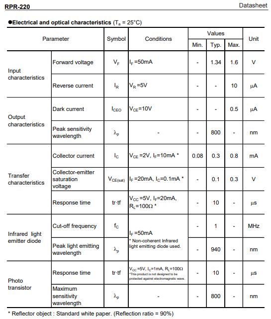
The data sheet can be downloaded here.
Circuit diagram of a reflective optical sensor
This is a schematic of the reflective optical sensor, the power supply, and the resistor.
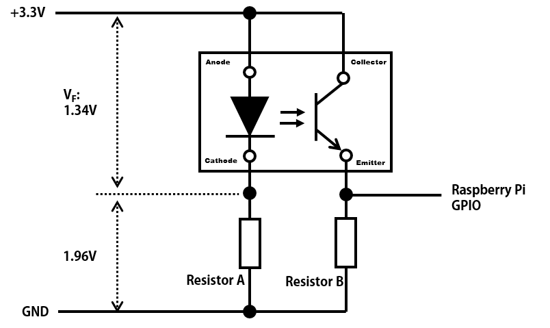
From this schematic and the current constraints on the GPIO pins of the Raspberry Pi, the value of the resistor is calculated.
the current constraints on the GPIO pins of the Raspberry Pi.
Note
- Maximum current per GPIO 1 pin is 16mA.
- When multiple GPIO pins are used, the total maximum current is 50 mA.
Calculation of resistance value A
From the data sheet, the VF of the LED is 1.34V.
So, 1.96V ( = 3.3V - 1.34V ) is applied to resistance A.
Maximum current per GPIO 1 pin is 16mA.
It is only a maximum value, so it should be 10 mA or less with a margin of error.
From Ohm's Law
R = V / I = 1.96[V] / 0.01[A] = 196[Ω]
When the resistance is 196 Ω or higher, the current is 10 mA or less.
I used a 330 ohm resistor that I had.
With a 330Ω resistor, the current value is 6mA.
Calculation of resistance value B
To calculate the value of resistor B, the Low / High threshold voltage of the GPIO pin of the Raspberry Pi must be considered.
Note
the Low / High threshold voltage of the GPIO pin of the Raspberry Pi
- High : 1.3V or higher
- Low : 0.8V or less
From the Low / High threshold voltages of the GPIO pins, two equations can be established.
1.3[V] < Ic min × R ・・・Equation 1
0.8[V] > Iceo max × R ・・・Equation 2
Ic : current of collector, Iceo : dark current, R : resistor value
Equation 1 : This condition is recognized as High on Raspberry Pi even when the current of collector "Ic" is minimum.
Equation 2 : This condition is recognized as Low on Raspberry Pi even when the dark current "Iceo" is maximum.
From these two equations, the resistance R is calculated.
According to the data sheet, Ic min is 0.08mA.
However, since the value of "Ic min" are based on the IF=10mA condition, it is necessary to recalculate "Ic min" to match the current conditions.
Under the present condition, IF is 6mA.
Ic min = 0.08[mA] × (6[mA] / 10[mA]) = 0.048mA
According to the data sheet, Iceo max is 0.5uA.
Based on the above conditions, R is as follows.
27[kΩ] < R < 1.6 [MΩ]
I used a 47kΩ resistor that I had.
sponsored link
Connection of each part
I show how to connect each part.
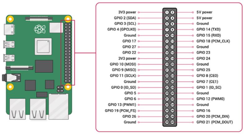
GPIO and the 40-pin Header on Raspberry Pi 4
Here is the pinout of the Raspberry Pi.
quotation : Raspberry Pi Documentation
Connection of each part
This is a schematic of the reflective optical sensor and Raspberry Pi.
A reflective optical sensor on the schematic is replaced by two LEDs.
( There is no part of reflective optical sensor on "Fritzing". )
On this schematic, white LED is "LED" and gray LED is "phototransistor".
Phototransistor is input to GPIO 17 (pin 11).
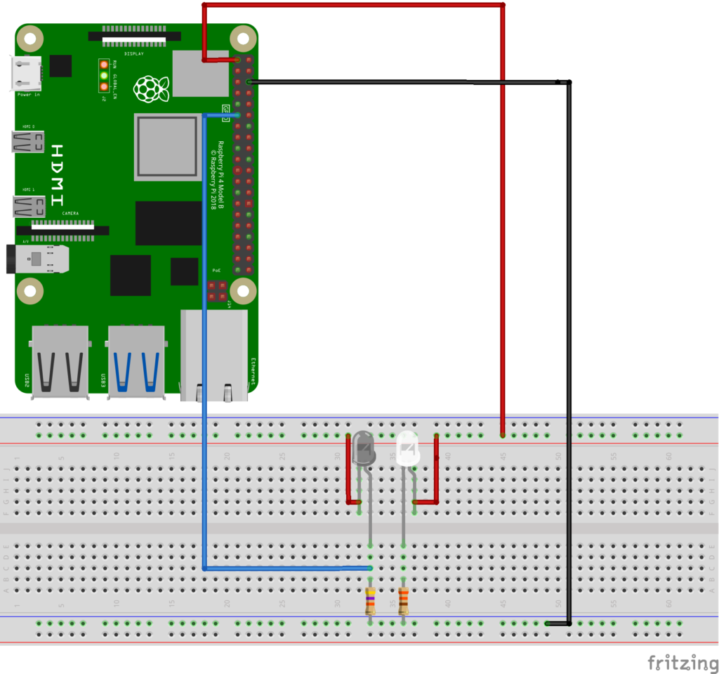
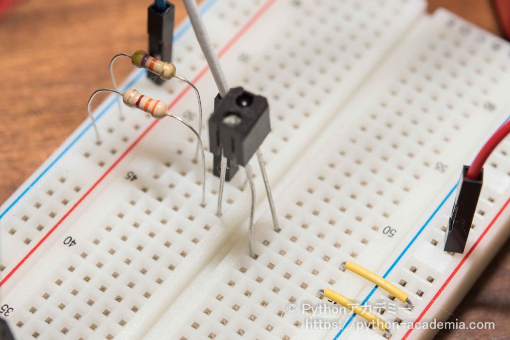
Picture of breadboard after wiring
sponsored link
Python sample code
Every second, the output of reflective optical sensor is read at the GPIO pin.
Press "ctrl" + "C" simultaneously to stop.
### sample code

import RPi.GPIO as GPIO
import time

GPIO.setmode(GPIO.BCM) #Specified by GPIO number
#GPIO.setmode(GPIO.BOARD) #Specified by Pin number

gpio_sensor = 17 #Specified by GPIO number
GPIO.setup(gpio_sensor,GPIO.IN) #Specified by "in mode"

time_start = time.time()

try :
    while True :

        ### ------------------- get_time ----------------- ###
        time_end = time.time()
        time_elapsed = time_end - time_start

        ### ------------------- GPIO input ----------------- ###
        input_sensor = GPIO.input(gpio_sensor)

        print('Time : {:.1f}s, GPIO_input : {}'.format(time_elapsed, input_sensor))
        print("")

        time.sleep(1)
except KeyboardInterrupt:
    print("\nCtrl+C")
    GPIO.cleanup(gpio_sensor)
This video shows the output of reflective optical sensor is acquired by Raspberry Pi.
sponsored link