The Raspberry Pi Pico is a small microcontroller board with two SPI controllers, two I2C controllers, two UARTs, and 16 PWMs.
The Raspberry Pi Pico is mainly used to control multiple devices as a master.
In fact, Raspberry Pi Pico also has a mode of slave operation.
This article shows how to set up Raspberry Pi Pico as I2C slave.
Contents
- Parts required to use the Raspberry Pi Pico
- Connection of each part
- Python sample code
sponsored link
Parts required to use the Raspberry Pi Pico
In the beginning, I show parts required to use the Raspberry Pi Pico reflective optical sensor.
Raspberry Pi Pico
Breadboard
This breadboard is a best seller on Amazon.
Jumper wire
This product is a set of male-male, male-female, and female-female.
sponsored link
Connection of each part
I show the wiring of Raspberry Pi and Raspberry Pi Pico.
SDA and SCL required for I2C communication are only connected.
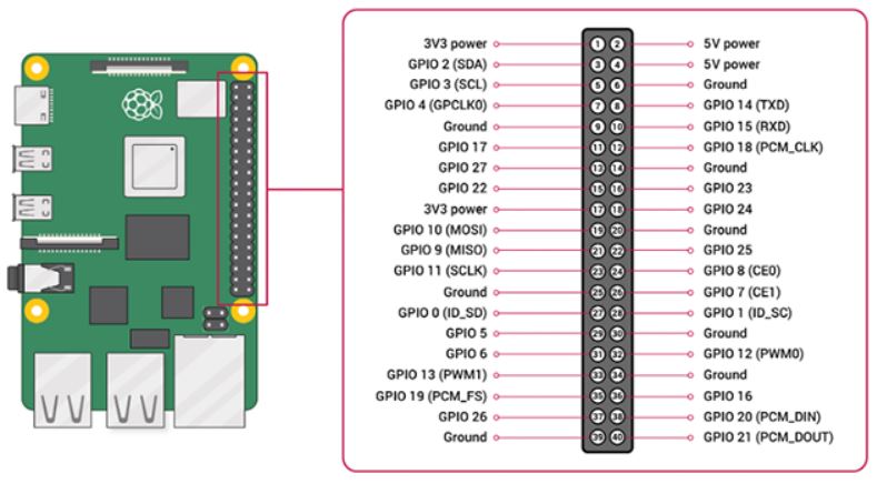
Raspberry Pi GPIO Pinout
Here is the pinout of the Raspberry Pi.
quotation : Raspberry Pi Documentation
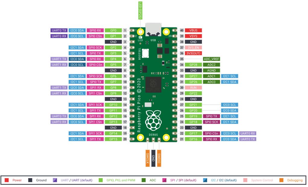
Raspberry Pi Pico GPIO Pinout
Here is the pinout of the Raspberry Pi Pico.
quotation : Raspberry Pi Pico Documentation
Connection of Raspberry Pi and Raspberry Pi Pico
This is a schematic of Raspberry Pi and Raspberry Pi Pico.
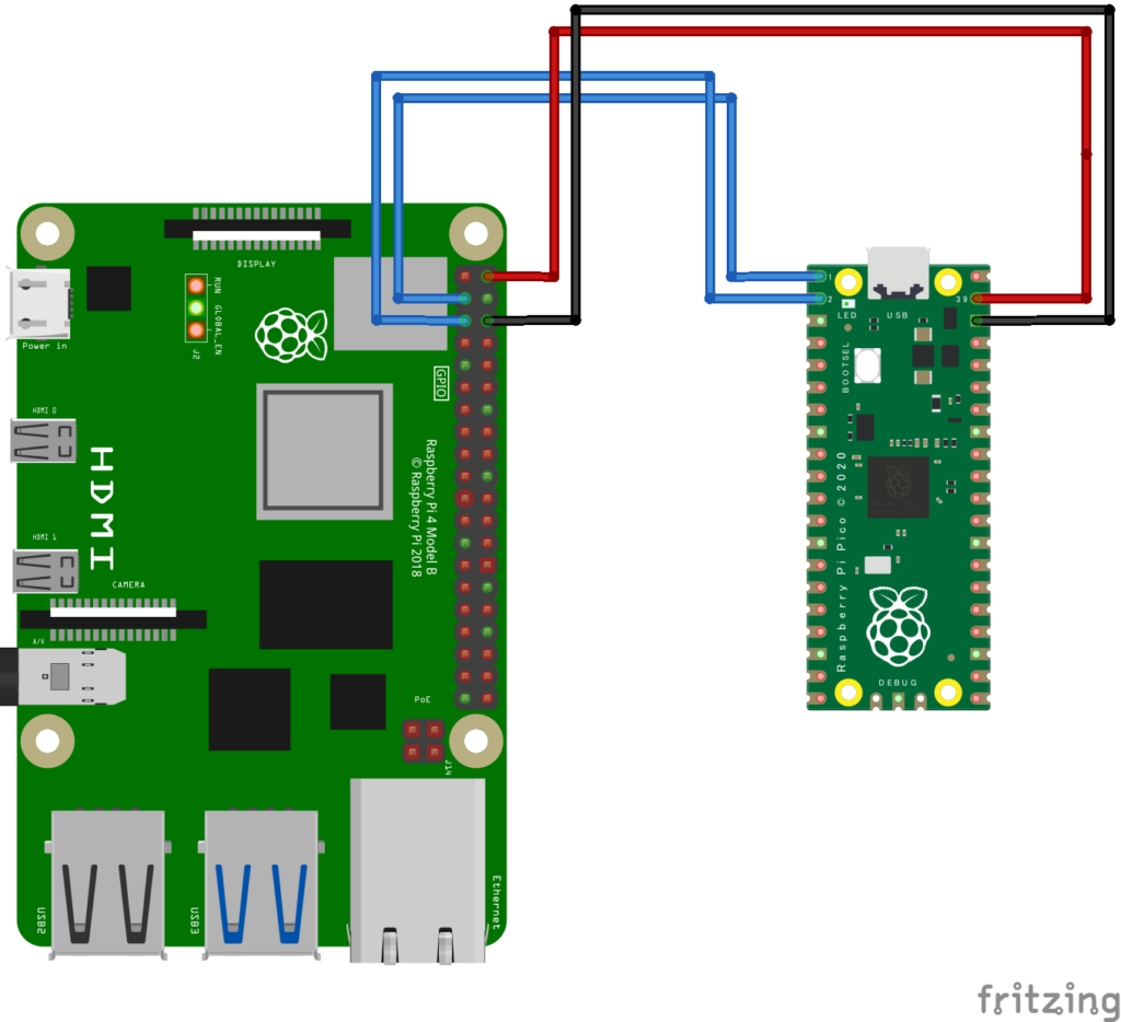
SDA and SCL required for I2C communication are only connected.
Since the input voltage of Raspberry Pi Pico is 1.8 ~ 5.5 V, 5 V power is supplied from Raspberry Pi.
sponsored link
Python sample code
I show sample code to run Raspberry Pi Pico in slave mode.
There are a few things to note.
【UF2】
In order to use the Raspberry Pi Pico, the MicroPython UF2 file must be installed.
Please install the UF2 file by referring to this site.
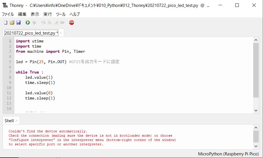
【Thonny】
For writing code to Raspberry Pi Pico, I recommend "Thonny" environment.
Thonny is Python Integrated development environment that makes it easy to write code to Raspberry Pi Pico.
MicroPython code to write to Raspberry pi pico
Prepare the following three files and write them to Raspberry Pi Pico.
- i2cSlave.py
- led.py
- main.py
Files stored in Raspberry Pi Pico can be viewed in Thonny.
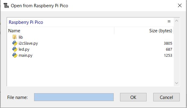
As soon as Raspberry Pi Pico is turned on, main.py starts up and calls led.py and i2cSlave.py.
The description of i2cSlave.py is based on this site.
Thanks to danjperron for creating this code.
--- i2cSlave.py ---
### i2cSlave.py
from machine import mem32,mem8,Pin

class i2c_slave:
    I2C0_BASE = 0x40044000
    I2C1_BASE = 0x40048000
    IO_BANK0_BASE = 0x40014000

    mem_rw = 0x0000
    mem_xor = 0x1000
    mem_set = 0x2000
    mem_clr = 0x3000

    IC_CON = 0 #I2C Control Register
    IC_TAR = 4 #I2C Target Address Register
    IC_SAR = 8 #I2C Slave Address Register

    IC_DATA_CMD = 0x10 #I2C Rx/Tx Data Buffer and Command Register

    IC_RAW_INTR_STAT = 0x34 # I2C Raw Interrupt Status Register

    IC_RX_TL = 0x38 #I2C Receive FIFO Threshold Register
    IC_TX_TL = 0x3C #I2C Transmit FIFO Threshold Register

    IC_CLR_INTR = 0x40 #Clear Combined and Individual Interrupt Register

    IC_CLR_RD_REQ = 0x50
    IC_CLR_TX_ABRT = 0x54

    IC_ENABLE = 0x6c #I2C ENABLE Register
    IC_STATUS = 0x70 #I2C STATUS Register


    def write_reg(self, reg, data, method=0):
        mem32[ self.i2c_base | method | reg] = data

    def set_reg(self, reg, data):
        self.write_reg(reg, data, method=self.mem_set)

    def clr_reg(self, reg, data):
        self.write_reg(reg, data, method=self.mem_clr)

    def __init__(self, i2cID = 0, sda=0, scl=1, slaveAddress=0x41):
        self.scl = scl
        self.sda = sda
        self.slaveAddress = slaveAddress
        self.i2c_ID = i2cID
        if self.i2c_ID == 0:
            self.i2c_base = self.I2C0_BASE
        else:
            self.i2c_base = self.I2C1_BASE

        # 1 Disable DW_apb_i2c
        self.clr_reg(self.IC_ENABLE, 1)

        # 2 set slave address
        # clr bit 0 to 9
        # set slave address
        self.clr_reg(self.IC_SAR, 0x1ff)
        self.set_reg(self.IC_SAR, self.slaveAddress &0x1ff)

        # 3 write IC_CON 7 bit, enable in slave-only
        self.clr_reg(self.IC_CON, 0b01001001)
        # set SDA PIN
        mem32[ self.IO_BANK0_BASE | self.mem_clr | ( 4 + 8 * self.sda) ] = 0x1f
        mem32[ self.IO_BANK0_BASE | self.mem_set | ( 4 + 8 * self.sda) ] = 3
        # set SLA PIN
        mem32[ self.IO_BANK0_BASE | self.mem_clr | ( 4 + 8 * self.scl) ] = 0x1f
        mem32[ self.IO_BANK0_BASE | self.mem_set | ( 4 + 8 * self.scl) ] = 3

        # 4 enable i2c
        self.set_reg(self.IC_ENABLE, 1)

    def anyRead(self):
        status = mem32[ self.i2c_base | self.IC_RAW_INTR_STAT] & 0x20
        if status :
            return True
        return False

    def put(self, data):
        # reset flag
        self.clr_reg(self.IC_CLR_TX_ABRT,1)
        status = mem32[ self.i2c_base | self.IC_CLR_RD_REQ]
        mem32[ self.i2c_base | self.IC_DATA_CMD] = data & 0xff

    def any(self):
        # get IC_STATUS
        status = mem32[ self.i2c_base | self.IC_STATUS]
        # check RFNE receive fifio not empty
        if (status & 8) :
            return True
        return False

    def get(self):
        while not self.any():
            pass
        return mem32[ self.i2c_base | self.IC_DATA_CMD] & 0xff


    if __name__ == "__main__":
        import utime
        from machine import mem32
        from i2cSlave import i2c_slave

        s_i2c = i2c_slave(0,sda=0,scl=1,slaveAddress=0x41)
        counter =1
        try:
            while True:
                if s_i2c.any():
                    print(s_i2c.get())
                if s_i2c.anyRead():
                    counter = counter + 1
                    s_i2c.put(counter & 0xff)

        except KeyboardInterrupt:
            pass
--- led.py ---
### led.py
import utime
import time
from machine import Pin, Timer


led = Pin(25, Pin.OUT)

def led_power_on() :

    for i in range(5) :

        led.value(1)
        time.sleep(0.5)
        led.value(0)
        time.sleep(0.5)
        led.value(1)
        time.sleep(0.5)
        led.value(0)
        time.sleep(1.0)

def led_on() :
        led.value(1)

def led_off() :
        led.value(0)
--- main.py ---
### main.py
import utime
import time
from machine import mem32,Pin
import led
from i2cSlave import i2c_slave

### --- check pico power on --- ###
led.led_power_on()

### --- pico connect i2c as slave --- ###
s_i2c = i2c_slave(0,sda=0,scl=1,slaveAddress=0x41)

try:
    while True:
        data = s_i2c.get()
        print(data)

        data_int = int(data)
        for i in range(data_int):
            led.led_on()
            time.sleep(0.5)
            led.led_off()
            time.sleep(0.5)


except KeyboardInterrupt:
    pass
Save above codes to the Raspberry Pi Pico.
I2C address of Raspberry Pi Pico
When main.py is loaded, I2C address of the Raspberry Pi Pico is recognized.
In the example in this article, I2C address is set to 0x41 in main.py.
Check if I2C address of Raspberry Pi Pico is really set to 0x41.
Enter the following command in Raspberry Pi terminal.
$ sudo i2cdetect -y 1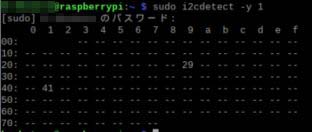
I2C address of Raspberry Pi Pico is 0x41.
Python code to write to Raspberry pi
Next, on the Raspberry Pi side, prepare the code for I2C communication.
--- pi_pico_i2c_test.py ---
### pi_pico_i2c_test.py
import time
import smbus

bus = smbus.SMBus(1)

bus.write_byte(0x41,3) #"3" is the data sent to Raspberry Pi Pico
When the above code is executed, LED of Raspberry Pi Pico blinks according to transmitted data.
sponsored link